3D Segmenting
The Segment tool can be used to split a 3D model into separate chunks or segments to allow them to be machined using a 3-axis CNC machine.
To get to the segmenting tool you first have to import a 3D model using the standard Model Import Dialog.
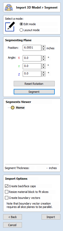
There are 4 main sets of options:
- The mode selection controls which mode we are in.
- The Segmenting Plane section controls the placement of the next segmenting plane. This is mostly for setting exact values. Most of the time, the 3D view controls are more convenient.
- The Segments Viewer gives an overview of the segmenting tree. This shows all of the segments and how they are related to one another.
- The Import Options can be used to control the settings used when we are ready to import the segmented model into the job.
 Usage Overview
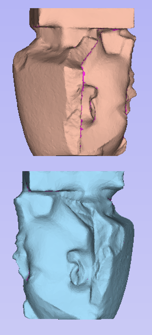
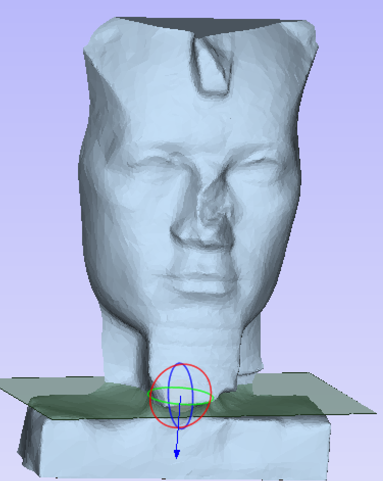
The segmenting tool works by incrementally splitting the imported model into blocks. The segmenting plane is placed in the model, and we press . Each segmenting operation produces two new segments, one for above the segmenting plane and one for below.
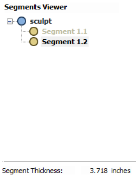
The Segments Viewer shows that this segmenting operation has produced two new segments. Each segment can be selected by clicking in the tree.
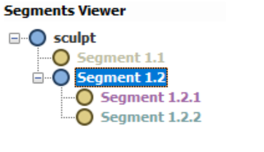
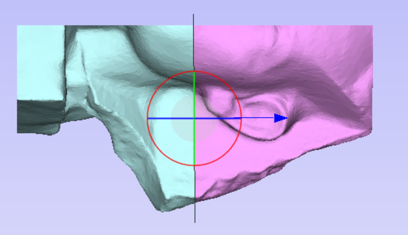
Once a segment has been selected it forms the base for future segmenting operations, and this segment can be further divided, into more segments. The tree reflects the fact that one of original segments has been chosen, and the tree and the parts in the 3D view are coloured to show the result.
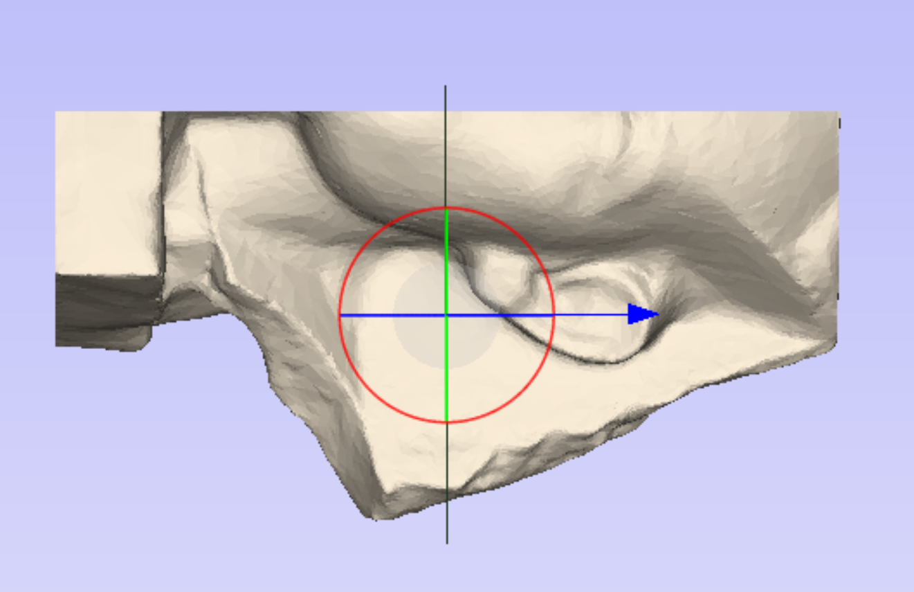
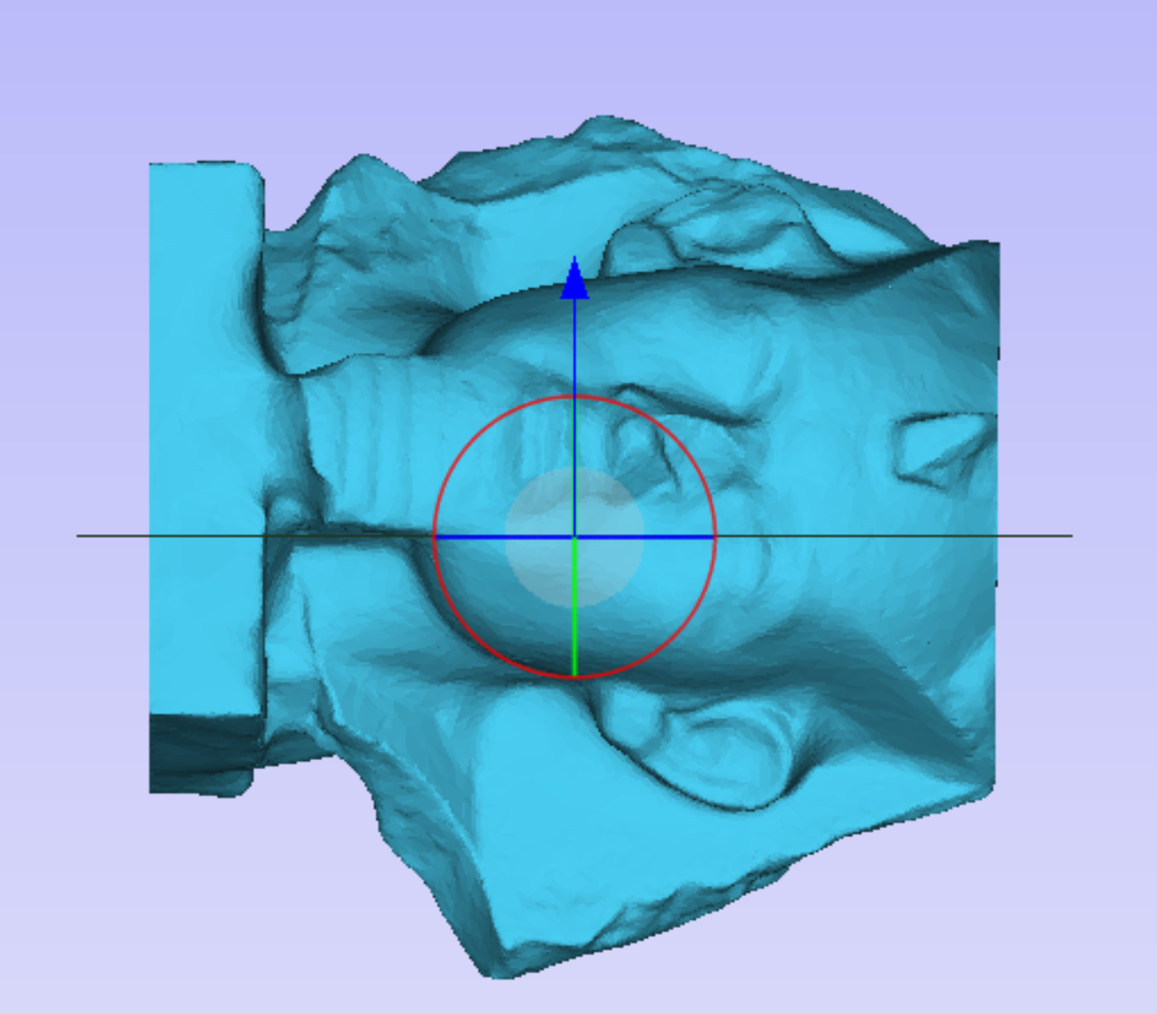
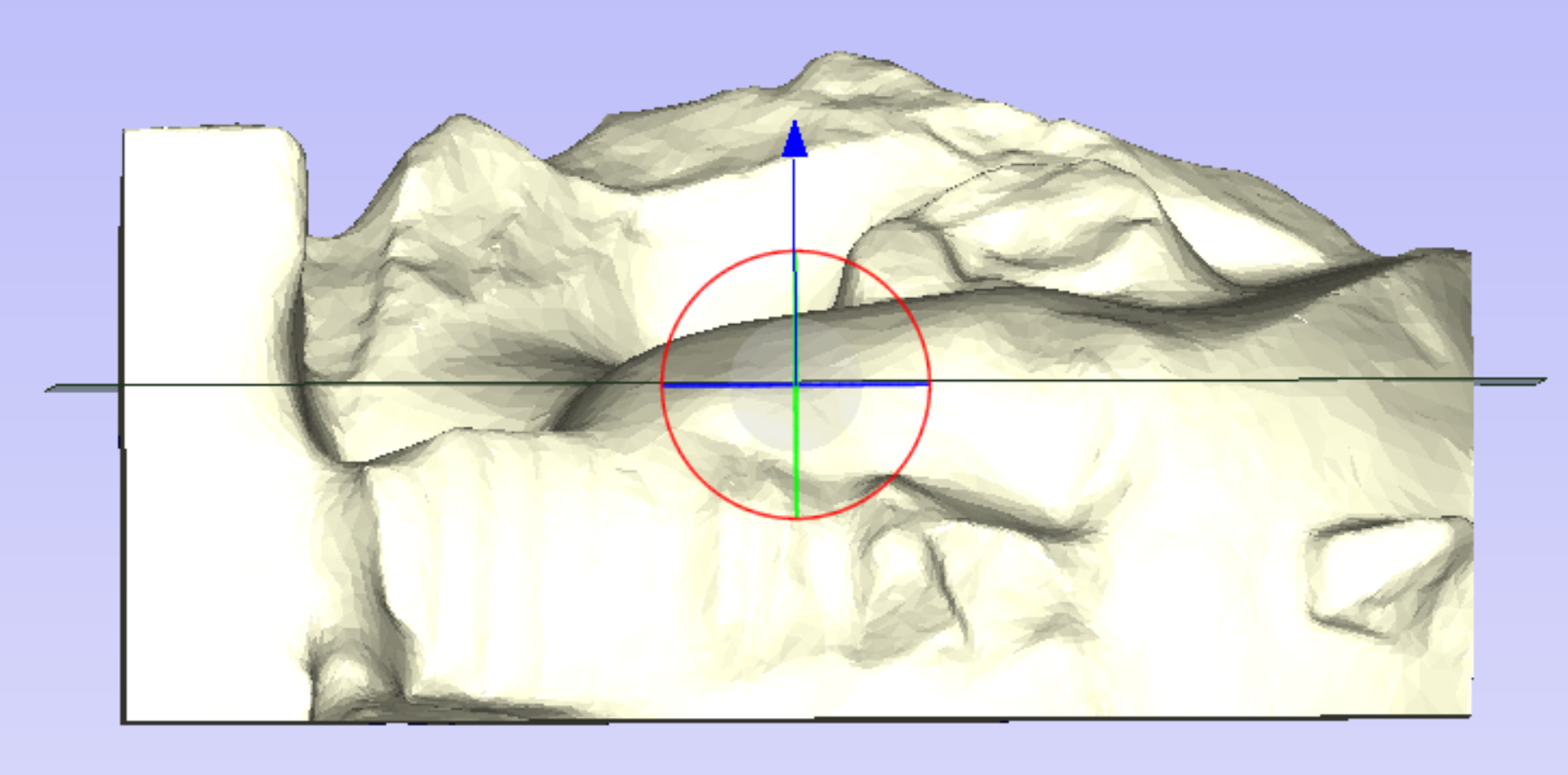
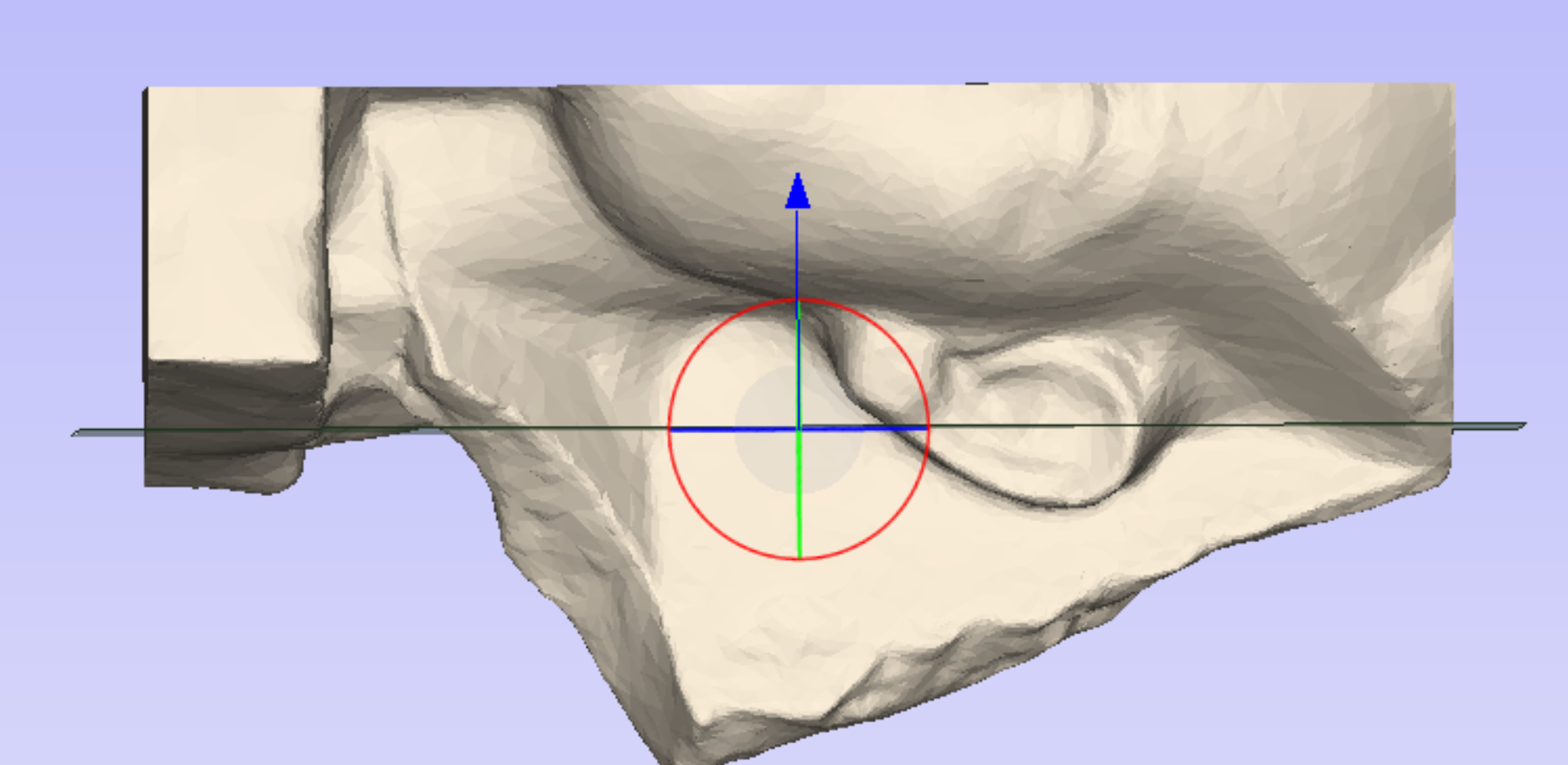
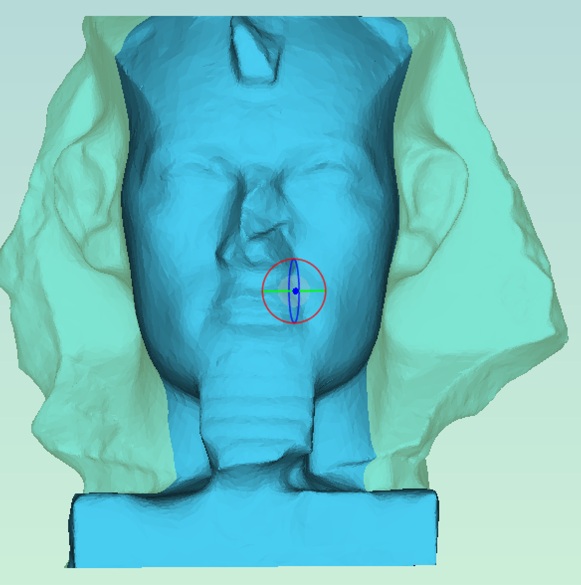
At each step the orientation and position of the segmenting plane can be adjusted to ensure that the resulting segments are appropriate for machining. To adjust the plane you can use one of the dynamic handles shown in the 3D view.
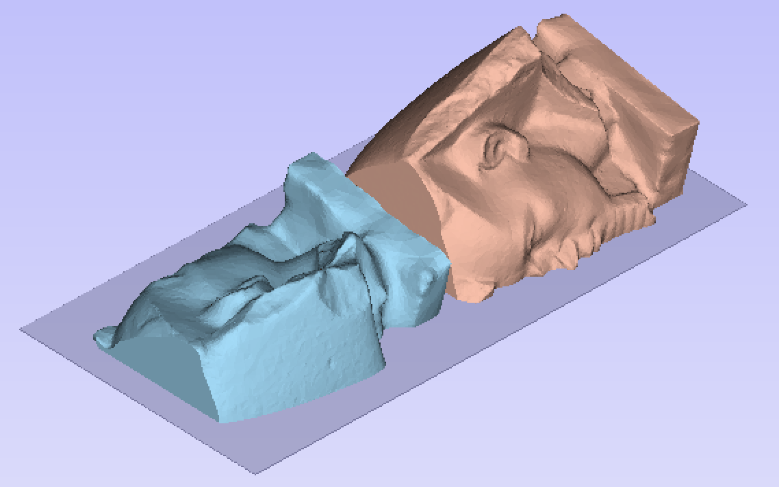
Once the model has been segmented enough then we can enter layout mode. Within layout mode we can see the segments created and how they will look once imported into the job.
At this stage each of the segments can be flipped to a desirable orientation. This is done by selecting a segment and cycling through the different possible orientations using the arrow buttons in the segment positioning section.

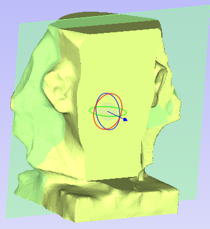
If it is desired to position the segment at an orientation which is not present in the provided cycle-through options, then the segment can be interactively rotated. Select the segment in question and press the shortcut on the keyboard. This will display a dynamic rotation handle centred on the selected segment which can be used to interactively orient it. Once you are happy with the positioning, press the keyboard shortcut once again to hide the rotation handle.
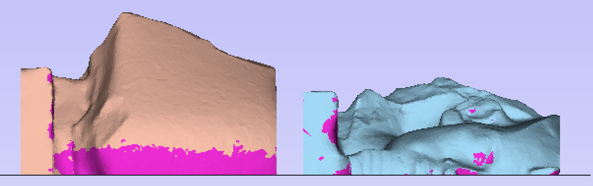
The other key feature of the layout mode is the visualize undercuts option. When this option is checked then undercut areas (which cannot be cut with a regular 3-axis CNC machine and so are ignored on import) are highlighted. If these areas are significant then it may be desirable to return to the edit mode and segment in a different way to remove these undercut areas.
With the dynamic nature of this tool we strongly recommend the viewing of the corresponding video tutorial for a more through coverage of the features
Note
If at any point errors occur with importing or undercut analysis then this might be caused by importing 3D models which have self-intersections. The segmenting tool cannot be used on such models.
Mode Selection
The mode selection switches the tool between layout and edit mode:
- In Edit mode the model can be segmented into different sized segments.
- In Layout mode the segments defined in edit mode can be rearranged, reoriented and visualized.
Segmenting Plane
The segmenting plane section controls the positioning of the next segmenting plane. This plane can be positioned using the 3D view controls, or by adjusting the numerical values in the edit boxes. Once a desired position and orientation have been chosen then pressing the button will produce a new segment.
Segments Viewer
The segments viewer section shows all of the segments in tree view. The root of this tree is the original model. Whenever a segmenting operation occurs then the current segment in the tree gets two children, these two children represent the resulting two segments produced when slicing along the segmenting plane.
At any point any of the segments in the tree can be selected. The 3D view will show only this segment. If this segment has been further segmented then those segments will be displayed visually by having different colours in the 3D view.
Undoing a segment
At any point any segmenting operation can be undone. To undo, select a segment from the tree, right-click and choose Delete children. This will remove the children from the tree and join the corresponding segments back together again.
Note
You can delete the children of any segment, this operation is not restricted to just the most-recently created segments. If at any point you want to restart segmenting altogether you can just delete the children of the top-level node.
Rearranging Segments
You can drag and drop segments on top of one another in the tree to merge two segments together. The resulting segment will just be the result of combining two segments. This can be useful for both recombining or rethinking a segmenting approach. It is also useful if you want to create a segment for a particular part, but that segment includes other parts you don't want.
Import Options
Create Backface Caps
If this option is selected then the back of any segment is closed off with a plane. This option may be desireable in mold creation.
Resize Material To Fit Slices
If this option is selected then the job size will be adjusted to accomodate the newly created segments.
Create boundary vectors
If this option is checked boundary vectors are created for the top and bottom boundaries of the segments.
Re-importing a segmented model
Once the segmented model has been imported it may be re-imported by right - clicking any of the imported segments in the component tree and selecting Re-import model. This will return the model to the last known state in the segmenting tool before import.